Dual-axis high-precision solar tracker controller SUNMAX ST-102
Basic Information
Dual-axis controller: |
Solar tracker controller SUNMAX ST-102 v.3.04 |
Tracking accuracy: |
About 0.0°0′15″ — 0.0°0′20″ (with a rigid supporting structure and without backlash) |
Tracking range: |
0°-350° (H - on horizontally) / 0°-90° (V - on vertically) |
Protection class: |
IP67 |
Temperature protection: |
Blocking the system from 0°C to -30°C |
Wind protection: |
Blocking the system from 7 m/s to 18.5 m/s |
Protection: |
Over current and short circuit protection |
Output power: |
DC24V / 2A, at peak up to 4A per motor |
Motors used: |
DC24V / 2A, equipped with Hall sensors |
Power Methods: |
Battery or stabilized external power supply |
Consumption current, max: |
up to 8A / DC24 |
Quiescent Current: |
≈ 3mA |
Battery charge current: |
≈ 0.8A (in the case of external charging) |
Feature of work: |
Motors can go into micro step mode |
Launch Feature: |
Smooth Start Engines |
Manual control: |
Control panel on the body of the controller of the solar tracker |
Feature of work: |
There is tracking the sun in cloudy weather (based on statistics) |
Solar sensor: |
SUNMAX SS-102 (sunlight is processed by a microcontroller) |
Tracker Case Dimensions: |
121x171x55mm |
Sensor Dimensions: |
70x82x105mm |
Total kit weight: |
115g |
Total weight, with box: |
1888gr |
Packing box size: |
200x300x100mm |
Controller SUNMAX ST-102
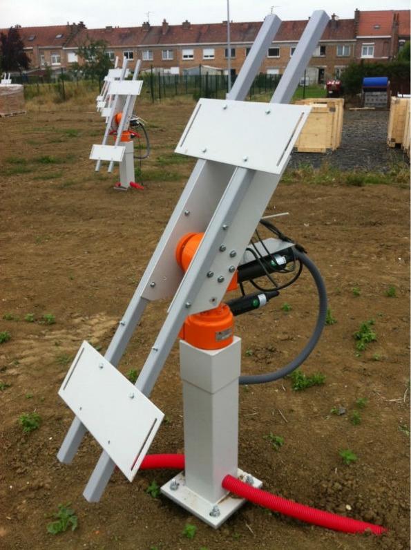
The high-precision biaxial solar controller is designed for positioning solar trackers for fiber-based sunlight transmission systems inside residential, industrial premises, bioreactors, etc. This solar controller can also be used for positioning trackers of conventional solar mono / polycrystalline panels, HCPV panels, solar parabolic / ring concentrators, solar heating collectors, photothermal, photovoltaic systems or various high-precision laboratory work related to tracking the position of the sun.
The radio electronic base of the solar tracker is assembled on low-current components and provides a very low current consumption of the system in standby mode, equal to about 3mA. DC motors, if necessary, switch to microstep with a soft start, which allows for high-precision positioning of the order of 0.0°0′15″ ч 0.0°0′20″. A keypad is mounted on the surface of the control unit housing to enable manual control of the movement of the solar tracker, setting threshold values for temperature and wind speed, determining possible errors and resetting them, as well as controlling the launch of updating the controller firmware.
Based on the accumulated statistics of the coordinates of the sun, a blind guidance mode for the daytime sun is provided at a time when the sun is covered by clouds. During the first day, statistics are accumulated and the tracking system self-learns. After that, the solar tracker will be able to adjust every 30 minutes under the sun in cloudy weather, to quickly capture the sun when it appears. Blind guidance is carried out by the solar tracker based on previously accumulated statistics of the coordinates of the sun without using GPS or GLONASS.
A CR2032 Lithium 3v battery is required to be installed in the controller case (designed to power the internal clock running in local solar time). For autonomous power supply of the controller, you can use rechargeable batteries 24V (12V minimum 12Ah - 2pcs). Batteries are not included and must be purchased by the buyer at the local store.
The solar tracker control system independently monitors the correct operation of all internal devices and connected peripherals, identifies possible malfunctions and reports them to the user by a combination of flashing light indicators on the control panel. To enable the emergency, stop of the tracker horizontally, before starting the system, it is recommended to connect a block of reed sensors of end positions, install a sensor magnet.
The solar tracker has a connector for connecting an anemometer (0-5V) to protect it from strong winds. The system puts the wearable structure in a horizontal position when the threshold of the set wind speed is exceeded for 15 seconds (the default is 15.3 m/s). Return to work occurs after a 4-minute decrease in wind speed of at least 25% of the set upper threshold speed (11.5 m/s by default).
The solar tracker has a sleep mode with low solar activity or a drop in temperature below the set value, the default is -30°C. Resumption of work occurs when the temperature rises to the default shutdown temperature + 3°C, that is, by default, the resumption of work will occur at -27°C.
The solar tracker is mounted on a support in front of the south and after connecting the power starts immediately to work. Solar tracker does not require pre-settings. However, if it is necessary to change the set upper threshold for limiting wind speed (default 15.3 m / s), lower temperature threshold (default -30 ° C), or to speed up the tracking of the tracker to the current area with resetting the previously accumulated statistics, you must appropriate settings according to the instructions below.
The solar tracker is designed to control serial gearboxes or any other home-made rotary systems, including those based on linear actuators with 24V / 2A motors with installed Hall sensors.
The solar tracker is designed, manufactured and tested to work unattended for many years of autonomous work anywhere in the world, in any hemisphere, from the north to the south pole.
You can use various power methods to power the tracker. From an external stabilized power supply DC 24V. When performing basic tasks that are not related to power generation, the system has enough power from a small mono / polycrystalline solar battery DC 36V with a capacity of 30-50W, with recharging of two series-connected 12V moto / car batteries with a capacity of ≈ 12 ч 55A. In practice, the YTX14-BS 12V 12Ah motor accumulators, as well as the LiFePO4 battery assemblies, have proven themselves well.
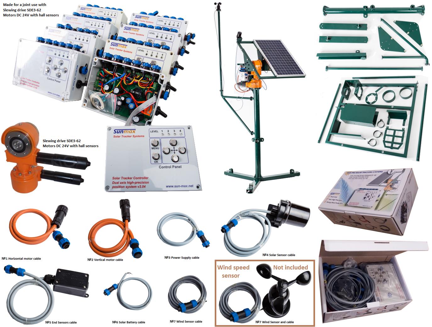
The solar tracker is equipped with all the necessary cables with RG-Connector connectors of class IP67 (including connectors for connecting on the motor side with equipped connectors WEIPU WA22J7Z1). HELUKABEL -40ч80°C high-quality connecting cables were used. The kit includes a two-axis solar sensor SUNMAX SS-102, reed switches of the end positions on the horizontal axis are supplied with a neodymium magnet in a plastic case, the end position sensors for the vertical axis are based on tilt sensors and are located inside the solar sensor body. The kit also includes an additional cover made of transparent plastic, if necessary, to increase the protection of the buttons on the control panel.
Control panel
To enter the solar tracker control menu, press the «Menu» button once. Confirmation of entry into the «Menu» will be the inclusion of L1. The necessary function is selected using the «Left» / «Right» buttons, which is accompanied by a switch of the light indicators from L1 to L2, from L2 to L3 and from L3 to L4. The selected function is activated by pressing the «OK» button once, the menu is exited by the «Menu» button. Confirmation of entry into the «Menu» will be a double blinking of all four light indicators.
Note. Before starting work, in order to accelerate the binding of the tracker controller to the coordinates of the terrain, it is strongly recommended to perform the procedure of forced reset of previously accumulated statistics. If this is not done forcibly, then the tracker controller on sunny days will do it on its own within 1-2 days. To fix the system to the terrain, according to the instructions below, it is necessary to manually install the solar sensor at about 45° to a position in the direction of approximately «South». Further, according to the instructions below, perform the binding to the area.
It is impossible to spoil the device with incorrect settings, it will still remain operational, the maximum that you can do by accident is to set low thresholds for blocking the device’s operation according to the temperature or wind threshold.
Work with the control panel
Manual control of the tracker is possible. To enter the control menu, you need to press the «Menu» button, then, if necessary, use the left / right arrow buttons to turn on the L1 lamp and press the «OK» button. Confirmation of entry into this mode is the alternate flashing of L1 and L4. When you press and hold one of the «Left» / «Right» / «Up» / «Down» buttons, the system is adjusted horizontally or vertically. The movement to the left is accompanied by the continuous illumination of the lamp L1, the movement to the right by the illumination of the lamp L4, the movement upward by the illumination of the lamp L1, the downward movement of the lamp L4. To return to the previous menu, you need to press the «Menu» button once, or press the «Menu» button two times, to completely exit the manual menu for controlling the solar tracker. If you do not press anything, then after 40 seconds, the tracker will exit the control menu on its own.
Short instructions for using manual control:
«Menu → on L1 → “OK» → further control of the «Left» / «Right» / «Up» / «Down» buttons.
Snap device to locality
Manually set the tracker approximately south at an angle to the horizon of about 45 degrees. Enter the menu by pressing the «Menu» button, then use the left / right arrow buttons to turn on the L4 lamp and press the «OK» button. Next, use the left / right arrow buttons to turn on the L3 lamp and press the «OK» button. Next, you need to sequentially press the «Left», «Right» and «OK» buttons. After which 3 flashes of all 4 light indicators will occur, which will indicate a complete reset of the accumulated statistics. To return to the previous menu, you need to press the «Menu» button once, or press the «Menu» button 3 times in a row to exit the solar tracker control menu completely. If you do not press anything, then after 40 seconds, the tracker will automatically exit the control menu.
Short instructions on binding the device to the locality:
«Menu» → «Right» → on L4 → «Ok» → «Right» → on L3 → «Ok» → then press the buttons «Left», «Right» and «Ok».
Setting the upper threshold wind speed for the 0-5V anemometer
Threshold Wind Speed Setting Table
№ The upper The upper threshold
profile voltage threshold, v of speed, m/s
0 1.012 7.0
1 1.397 8.3
2 1.782 9.5
3 2,167 10.7
4 2.552 11.9
5 2.937 13.1
6 3.322 14.2
7 3.707 15.3
8 4.092 16.4
9 4.477 17.5
10 4.862 18.5
To set the upper threshold wind speed, press the «Menu» button to enter the menu. Next, use the left / right arrow buttons to turn on the L4 lamp and press the «OK» button. Next, use the left / right arrow buttons to turn on the L2 lamp and press the «OK» button. You have entered the menu for setting the upper threshold for wind speed. A single press of the button with the «Down» arrow will reset any current profile immediately to profile No. 0, which is confirmed by a single flash of lamp L1. The next time you press the «Up» button, a one-step transition from the current profile to the next, higher profile occurs, which is confirmed by a single flash of the L4 lamp. After setting the required profile, to completely exit this settings menu, you need to press the «Menu» button 3 times. The default profile is profile number 7.
Short instructions for setting the upper threshold for wind speed:
«Menu» → «Right» → on L4 → «Ok» → «Right» → on L2 → «Ok» → then the buttons «Up» or «Down».
Setting the lower temperature threshold
Low threshold temperature setting table
№ Lower temperature
profile threshold, °C
0 0.0
1 -3.0
2 -6.0
3 -9.0
4 -12.0
5 -15.0
6 -18.0
7 -21.0
8 -24.0
9 -27.0
10 -30.0
To set the lower threshold temperature, press the «Menu» button to enter the menu. Next, use the left / right arrow buttons to turn on the L4 lamp and press the «OK» button. Next, use the left / right arrow buttons to turn on the L4 lamp and press the «OK» button. You have entered the menu for setting the lower temperature threshold. A single press of the button with the Down arrow will reset any current profile immediately to profile No. 0, which is confirmed by a single flash of lamp L1. The next time you press the «Up» button, a one-step transition from the current profile to the next, higher profile occurs, which is confirmed by a single flash of the L4 lamp. After setting the required profile, to completely exit this settings menu, you need to press the «Menu» button 3 times. The default profile is profile number 10.
Short instructions for setting the lower temperature threshold:
«Menu» → «Right» → on L4 → «Ok» → «Right» → on L4 → «Ok» → then the buttons «Up» or «Down».
Error indication and reset mode.
If the lamp L1 starts flashing spontaneously non-intensively (approximately 1 turn-on per second), this means the occurrence / presence of an error. The type of error can be viewed and then reset in the error display menu. To enter the error display menu, you need to press the «Menu» button, then use the left / right arrow buttons to select the L4 lamp and press the «OK» button. Next, use the left / right arrow buttons to select the L1 lamp and click «OK». After that, an error code will be displayed by a combination of a group of flashing lamps L1-L4. It is necessary to identify this error, check the corresponding peripheral device, and eliminate the cause of the error. To reset this error, you need to click the «OK» button. To return to the previous menu, you need to press the «Menu» button once, or press the «Menu» button two times, to completely exit the solar tracker control menu. If you do not press anything, then after 40 seconds, the tracker will automatically exit the control menu.
Short instructions for reading and resetting errors:
«Menu» → «Right» → on L4 → «Ok» → «Right» → on L1 → «Ok» → Make reading a error → push to reset «Ok».
Error information on the display panel with decoding of error codes
Combination of flashing lights before entering the ERROR MENU
L1 |
L2 |
L3 |
L4 |
|
○ |
● |
○ |
○ |
Error, power supply, repeated series of frequent flashes of the L2 lamp |
● |
○ |
○ |
○ |
Controller error, flashing lamp L1 |
Combination of flashing lights after entering the ERROR MENU (about 1 flash per second)
L1 |
L2 |
L3 |
L4 |
|
● |
○ |
○ |
○ |
Error №. 01, solar sensor malfunction |
○ |
● |
○ |
○ |
Error №. 02, there is no horizontal motor rotation (H) |
● |
● |
○ |
○ |
Error №. 03, there is no rotation of the vertical motor (V) |
○ |
○ |
● |
○ |
Error №. 04, 12C bus failure |
● |
○ |
● |
○ |
Error №. 05, open / short circuit of the sensor of the end left position |
○ |
● |
● |
○ |
Error №. 06, open/short circuit of the sensor of the right end position |
● |
● |
● |
○ |
Error №. 07, there is no reading of the Hall sensors of the motor (Н). |
○ |
○ |
○ |
● |
Error №. 08, there is no reading of the Hall sensors of the motor (V). |
● |
○ |
○ |
● |
Error №. 09, high the voltage of the power source |
● |
● |
● |
● |
Error №. 10, motor overload current |
! Errors are reset only after checking and troubleshooting !
NOTE:
When the power is turned on, the L2 lamp flashes for 5 seconds, if there is no power error, the flashing of this lamp stops. Then, the L1 lamp blinks for another 5 seconds, if no controller errors are detected, the blinking of this lamp also stops and the tracker returns to its normal operating state. When the power is turned off for some time (until the capacitors are completely discharged), the L2 lamp flashes.
ATTENTION!
Error, the power source is accompanied by a series of frequent flashes of the L2 lamp. The series consists of 15 flashes of an L2 lamp with a frequency of approximately 3 flashes per second for 5 seconds and 1 second pause. Then a series of flashes repeats, which indicates a previous two-time failure or forced power off within 1 day. The reset of the power error is eliminated by pressing and holding the «OK» button for about 5 seconds, until the frequent flashing of L2 stops. After that, the power and full work of the tracker controller resumes.
When the power source and solar panel are connected, it is not recommended to press the Menu button; if you accidentally enter the firmware update mode, you need to turn off the power toggle switch and turn on the controller again.
Short instructions for resetting the device power error:
Frequent flashing «L2» → holding the «Ok» button for 5 seconds → disabling «L2» → power is restored.
Device firmware update
If necessary, using the USB RS232 adapter (5V) of the PIC18 Firmware updater software for Windows environment, you can update the firmware of the SUNMAX ST-102 v.3.04 controller.
Short instructions on entering the device firmware mode:
When turning on the power of the USB Adapter, press and hold the «Menu» button → «L2 flashing» → «L2 glow»
To update the controller firmware, you must do the following:
On the device:
1. Disconnect the charge plug from the solar battery.
2. Disconnect the power plug from the battery or the power toggle switch.
3. Connect single outputs (red, green, white, black) of the USB RS232 adapter (5V) to the controller board.
On the computer:
1. Connect the USB adapter to the computer and install the driver of the USB adapter.
2. Reconnect the USB adapter to the computer (the L2 lamp flashes on the device).
On the device:
1. Press and hold the «Menu» button for 5 seconds, until L2 transitions from blinking to a continuous glow.
On the computer:
1. Run the PIC18 Firmware updater firmware update program.
2. Select the COM port corresponding to the virtual port of the USB adapter and click the «Connect» button. If the port is selected correctly, the message Encrypted bootloader appears, if the message does not appear, you need to disconnect the device with the same button and find the corresponding COM port.
3. Next, select the firmware file and click the «Update» button.
4. During the firmware, the progress bar of the program bar moves and the L3 and L4 lamps flash on the device.
5. At the end of the firmware process, L3 and L4 on the device stop flashing.
6. Close the firmware program PIC18 Firmware updater.
7. Disconnect the USB adapter from the computer.
8. Next, disconnect the USB adapter from the device.
9. Connect the power to the device.
10. The device is ready for operation.
In the event of a failure when flashing the device due to the disconnection of the wire or power, its operability is not lost, you need to reconnect the wires or power in a qualitative manner and perform a second firmware upgrade.
Download Software for Firmware Update
Download the controller firmware update program.
Download the latest SUNMAX ST-102 firmware.
Download technical description SUNMAX ST-102 (pdf).
Dual-axis high precision solar tracker controller SUNMAX ST-102
Packing List
1 |
Solar Tracker Controller SUNMAX ST-102 v.3.04 |
607g |
|
2 |
Additional transparent protective cover |
132g |
|
3 |
Horizontal motor cable № 1 |
180g |
1.0m, Ø cable = 9.0 mm |
4 |
Vertical motor cable № 2 |
179g |
1.0m. Ø cable = 9.0 mm |
5 |
Power Supply cable № 3 |
86g |
1.0m Ø cable = 6.8 mm |
6 |
Solar Sensor cable № 4 with Solar Sensor |
234g |
1.5m Ø cable = 7.0 mm |
7 |
End Position Sensors cable № 5 with End Position Sensors |
127g |
1.0m Ø cable = 6.3 mm |
8 |
Solar Battery cable № 6 |
43g |
1.0m Ø cable = 5.6 mm |
9 |
Wind Sensor cable № 7 |
71g |
2.5m Ø cable = 4.3 mm |
10 |
Magnet for End Sensors in shell |
17g |
|
|
Box: |
212g |
|
|
Total: |
1888g |
|
The purpose of the connectors on the Right Side and Back panel.